
 Telecommunications
 FTTX
FTTX Data Centers
 Integrated Networks
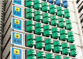 Fiber Optic Connectivity
100G-QSFP28-CWDM4 is a Four-Channel, Pluggable, dual LC, Fiber-Optic QSFP28 Transceiver for 100G Ethernet applications. The QSFP28 full-duplex optical module offers 4 independent transmit and receive channels, each capable of 26Gbps operation for an aggregate data rate of 104Gbps 2km using single mode fiber. These 100G-QSFP28-CWDM4 are designed to operate over single mode fiber systems using 1310nm DFB laser array. Huihongfiber QSFP28 CWDM4 is one kind of transceiver which provides increased port density and total system cost savings. They are compliant with the QSFP28 MSA, CWDM4 MSA and portions of IEEE P802.3bm.

100G QSFP28 CWDM4 Features
Four-channel full-duplex transceiver modules
Transmission data rate up to 26Gbit/s per channel
Up to 2km transmission of single mode fiber
Low power consumption <3.5W
Operating case temperature 0°C to +70°C
3.3V power supply voltage
RoHS 6 compliant
Hot Pluggable QSFP form factor
LC connector receptacle
Built-in digital diagnostic function
100G QSFP28 CWDM4 Applications
100G Ethernet
Proprietary High Speed Interconnections
Data center
Absolute Maximum Ratings
The operation in excess of any absolute maximum ratings might cause permanent damage to this module.
| Parameter | Symbol | Min | Max | Unit | Note |
| Storage Temperature | TST | -40 | 85 | degC | |
| Relative Humidity(non-condensing) | RH | 0 | 85 | % | |
| Operating Case Temperature | TOPC | 0 | 70 | degC | |
| Supply Voltage | VCC | -0.3 | 3.6 | V | |
| Input Voltage | Vin | -0.3 | Vcc+0.3 | V |
Recommended Operating Conditions and Supply Requirements
| Parameter | Symbol | Min | Typical | Max | Unit |
| Operating Case Temperature | TOPC | 0 | 70 | degC | |
| Power Supply Voltage | VCC | 3.13 | 3.3 | 3.47 | V |
| Power Consumption | – | 3.5 | W | ||
| Data Rate | DR | 25.78125 | Gbps | ||
| Data Speed Tolerance | ∆DR | -100 | +100 | ppm | |
| Link Distance with G.652 | D | 0 | 2 | km |
Optical Characteristics
All parameters are specified under the recommended operating conditions with PRBS31 data pattern unless otherwise specified.
| Symbol | Min | Typical | Max | Unit | Notes | ||||||
| L0 | 1264.5 | 1271 | 1277.5 | nm | |||||||
| L1 | 1284.5 | 1291 | 1297.5 | nm | |||||||
| L2 | 1304.5 | 1311 | 1317.5 | nm | |||||||
| L3 | 1324.5 | 1331 | 1337.5 | nm | |||||||
| λrms | – | 3.5 | nm | 1 | |||||||
| PAVG | -4 | -0.5 | +2.5 | dBm | |||||||
| lane | |||||||||||
| Optical Modulation
Amplitude (OMA) |
POMA | -4 | -0.5 | +2.5 | dBm | ||||||
| Difference in Launch Power between any two lanes | Ptx,diff | 4.0 | dB | ||||||||
| Transmitter and Dispersion
Penalty per Lane |
TDP | 3 | dBm | ||||||||
| Rise/Fall Time | Tr/Tf | 30 | ps | ||||||||
| Extinction Ratio | ER | 3.5 | dB | ||||||||
| Transmitter Reflectance | RT | -12 | dB | ||||||||
| Transmitter Eye Mask Margin | EMM | 10 | % | ||||||||
| Average Launch Power OFF
Transmitter, each Lane |
Poff | -30 | dBm | ||||||||
| Transmitter Eye Mask
Definition {X1, X2, X3, Y1, Y2, Y3} |
{0.31,
0.4, 0.45, 0.34, 0.38, 0.4} |
||||||||||
| Parameter | Symbol | Min | Typical | Max | Unit | ||||||
| Wavelength Assignment | L0 | 1264.5 | 1271 | 1277.5 | nm | ||||||
| L1 | 1284.5 | 1291 | 1297.5 | nm | |||||||
| L2 | 1304.5 | 1311 | 1317.5 | nm | |||||||
| L3 | 1324.5 | 1331 | 1337.5 | nm | |||||||
| Damage Threshold | THd | +3 | dBm | ||||||||
| Overload, each lane | OVL | +2.5 | dBm | ||||||||
| Receiver Sensitivity in OMA, each Lane | SEN | -10 | dBm | ||||||||
| Signal Loss Assert Threshold | LOSA | -30 | dBm | ||||||||
| Signal Loss Deassert
Threshold |
LOSD | -12 | dBm | ||||||||
| LOS Hysteresis | LOSH | 0.5 | 1.5 | 6 | dB | ||||||
| Optical Return Loss | ORL | -12 | dBm | ||||||||
Notes:
- Transmitter wavelength, RMS spectral width and power need to meet the OMA minus TDP specs to guarantee link performance.
- The eye diagram is tested with 1000 waveform.
- Sensitivity is specified at 5×10⁻⁵ BER.
Electrical Specifications
| Parameter | Symbol | Min | Typical | Max | Unit |
| Differential input impedance | Zin | 90 | 100 | 110 | ohm |
| Differential Output impedance | Zout | 90 | 100 | 110 | ohm |
| Differential input voltage amplitude | ΔVin | 300 | 1100 | mVp-p | |
| Differential output voltage amplitude | ΔVout | 500 | 800 | mVp-p | |
| Input Logic Level High | VIH | 2.0 | VCC | V | |
| Input Logic Level Low | VIL | 0 | 0.7 | V | |
| Output Logic Level High | VOH | VCC-0.5 | VCC | V | |
| Output Logic Level Low | VOL | 0 | 0.4 | V |
Pin Descriptions
| PIN | Logic | Symbol | Name/Description | Note |
| 1 | GND | Ground | 1 | |
| 2 | CML-I | Tx2n | Transmitter Inverted Data Input | |
| 3 | CML-I | Tx2p | Transmitter Non-Inverted Data output | |
| 4 | GND | Ground | 1 | |
| 5 | CML-I | Tx4n | Transmitter Inverted Data Input | |
| 6 | CML-I | Tx4p | Transmitter Non-Inverted Data output | |
| 7 | GND | Ground | 1 | |
| 8 | LVTLL-I | ModSelL | Module Select | |
| 9 | LVTLL-I | ResetL | Module Reset | |
| 10 | VccRx | ﹢3.3V Power Supply Receiver | 2 | |
| 11 | LVCMOS-I/O | SCL | 2-Wire Serial Interface Clock | |
| 12 | LVCMOS-I/O | SDA | 2-Wire Serial Interface Data | |
| 13 | GND | Ground | ||
| 14 | CML-O | Rx3p | Receiver Non-Inverted Data Output | |
| 15 | CML-O | Rx3n | Receiver Inverted Data Output | |
| 16 | GND | Ground | 1 | |
| 17 | CML-O | Rx1p | Receiver Non-Inverted Data Output | |
| 18 | CML-O | Rx1n | Receiver Inverted Data Output | |
| 19 | GND | Ground | 1 | |
| 20 | GND | Ground | 1 | |
| 21 | CML-O | Rx2n | Receiver Inverted Data Output | |
| 22 | CML-O | Rx2p | Receiver Non-Inverted Data Output | |
| 23 | GND | Ground | 1 | |
| 24 | CML-O | Rx4n | Receiver Inverted Data Output | 1 |
| 25 | CML-O | Rx4p | Receiver Non-Inverted Data Output | |
| 26 | GND | Ground | 1 | |
| 27 | LVTTL-O | ModPrsL | Module Present | |
| 28 | LVTTL-O | IntL | Interrupt | |
| 29 | VccTx | +3.3 V Power Supply transmitter | 2 | |
| 30 | Vcc1 | +3.3 V Power Supply | 2 | |
| 31 | LVTTL-I | LPMode | Low Power Mode | |
| 32 | GND | Ground | 1 | |
| 33 | CML-I | Tx3p | Transmitter Non-Inverted Data Input | |
| 34 | CML-I | Tx3n | Transmitter Inverted Data Output | |
| 35 | GND | Ground | 1 | |
| 36 | CML-I | Tx1p | Transmitter Non-Inverted Data Input | |
| 37 | CML-I | Tx1n | Transmitter Inverted Data Output | |
| 38 | GND | Ground | 1 |
Notes:
- Module circuit ground is isolated from module chassis ground within the module. GND is the symbol for signal and supply (power) common for QSFP modules.
- The connector pins are each rated for a maximum current of 500mA.
ModSelL Pin
The ModSelL is an input pin. When held low by the host, the module responds to 2-wire serial communication commands. The ModSelL allows the use of multiple QSFP modules on a single 2-wire interface bus. When the ModSelL is “High”, the module will not respond to any 2-wire interface communication from the host. ModSelL has an internal pull-up in the module.
ResetL Pin
Reset. LPMode_Reset has an internal pull-up in the module. A low level on the ResetL pin for longer than the minimum pulse length (t_Reset_init) initiates a complete module reset, returning all user module settings to their default state. Module Reset Assert Time (t_init) starts on the rising edge after the low level on the ResetL pin is released. During the execution of a reset (t_init) the host shall disregard all status bits until the module indicates a completion of the reset interrupt. The module indicates this by posting an IntL signal with the Data_Not_Ready bit negated. Note that on power up (including hot insertion) the module will post this completion of reset interrupt without requiring a reset.
LPMode Pin
Huihongfiber CWDM4 operate in the low power mode (less than 1.5 W power consumption) This pin active high will decrease power consumption to less than 1W.
ModPrsL Pin
ModPrsL is pulled up to Vcc on the host board and grounded in the module. The ModPrsL is asserted “Low” when the module is inserted and deasserted “High” when the module is physically absent from the host connector.
IntL Pin
IntL is an output pin. When “Low”, it indicates a possible module operational fault or a status critical to the host system. The host identifies the source of the interrupt by using the 2-wire serial interface. The IntL pin is an open collector output and must be pulled up to Vcc on the host board.
Power Supply Filtering
The host board should use the power supply filtering shown in Figure1.
Figure1. Host Board Power Supply Filtering
Diagnostic Monitoring Interface
Digital diagnostics monitoring function is available on all Huihongfiber QSFP28 CWDM4. A 2-wire serial interface provides user to contact with module. The structure of the memory is shown in Figure 3. The memory space is arranged into a lower, single page, address space of 128 bytes and multiple upper address space pages. This structure permits timely access to addresses in the lower page, such as Interrupt Flags and Monitors. Less time critical time entries, such as serial ID information and threshold settings, are available with the Page Select function. The interface address used is A0xh and is mainly used for time critical data like interrupt handling in order to enable a one-time-read for all data related to an interrupt situation. After an interrupt, IntL, has been asserted, the host can read out the flag field to determine the affected channel and type of flag.
| Parameter | Symbol | Min | Max | Unit | Notes |
| Temperature monitor absolute error | DMI_Temp | -3 | +3 | degC | Over operating temp |
| Supply voltage monitor absolute error | DMI _VCC | -0.1 | 0.1 | V | Full operating range |
| Channel RX power monitor absolute error | DMI_RX | -3 | 3 | dB | Per channel |
| Channel Bias current monitor | DMI_Ibias | -10% | 10% | mA | Per channel |
| Channel TX power monitor absolute error | DMI_TX | -3 | 3 | dB | Per channel |
Figure 3
EEPROM Serial ID Memory Contents:
| Data
Address (Dec) |
Name of Field | Description | Value(Hex) |
| Base ID Fields | |||
| 128 | Identifier | QSFP28 | 0E |
| 129 | Extended
Identifier |
3.5W max. power consumption | CC |
| 130 | Connector type | LC Connector | 0C |
| 131 | Transceiver
Application supported |
Reserved | 80 |
| 132 | 0 | ||
| 133 | 0 | ||
| 134 | Reserved | 0 | |
| 135 | Intermediate distance | 20 | |
| 136 | Shortwave laser w/o OFC (SN) | 10 | |
| 137 | Single Mode (SM) | 01 | |
| 138 | 1200 Mbytes/Sec | 80 | |
| 139 | Encoding | NRZ | 03 |
| 140 | BR, nominal | Nominal bit rate | 67 |
| 141 | Rate Select | QSFP Rate Select Version 1 | 0 |
| 142 | Link
Length(Standard SM Fiber) |
2KM | 2 |
| 143 | Link
Length(OM3) |
Not supported | 0 |
| 144 | Link
Length(OM2) |
Not supported | 0 |
| 145 | Link
Length(OM1) |
Not supported | 0 |
| 146 | Link Length(Cooper) | Not supported | 0 |
| 147 | Device Tech | Uncooled transmitter device;1310nm DFB; No wavelength control; PIN detector; Transmitter not tunable | 40 |
| 148 | 52 | ||
| 149 | 41 | ||
| 150 | Vendor Name | HUIHONGFIBER | 59 |
| 151 | 4F | ||
| 152 | 50 | ||
| 153 | 54 | ||
| 154 | 45 | ||
| 155 | 4B | ||
| 156 | |||
| 157 | |||
| 158 | |||
| 159 | |||
| 160 | |||
| 161 | |||
| 162 | |||
| 163 | |||
| 164 | Electronic or optical
interfaces for InfiniBand |
4x SDR Speed(2.5Gb/s),DDR Speed(5.0Gb/s),QDR Speed(10Gb/s). | 7 |
| 165 | Vendor OUI | 00 | 00 |
| 166 | 00 | 00 | |
| 167 | 00 | 00 | |
| 168 | Vendor PN | ||
| 169 | |||
| 170 | |||
| 171 | |||
| 172 | |||
| 173 | |||
| 174 | |||
| 175 | |||
| 176 | |||
| 177 | |||
| 178 | |||
| 179 | |||
| 180 | |||
| 181 | |||
| 182 | |||
| 183 | |||
| 184 | Vendor Rev | REV.1A | 31 |
| 185 | 41 | ||
| 186 | Wavelength | 1310nm | 66 |
| 187 | 58 | ||
| 188 | Wavelength
Tolerance |
±50 | 0B |
| 189 | B8 | ||
| 190 | Max Case Temp | Max Case Temp 70°C | 46 |
| 191 | Check Sum | Address 128-190 | |
| Extended ID Fields | |||
| 192 | Options | Rate Select, TX Disable, TX Fault, LOS,
Warning indicators for: Temperature, VCC, RX power, TX Bias |
0 |
| 193 | 0 | ||
| 194 | 0 | ||
| 195 | DE | ||
| 196 | Vendor SN | Serial number provided by vendor(ASCII) | |
| 197 | |||
| 198 | |||
| 199 | |||
| 200 | |||
| 201 | |||
| 202 | |||
| 203 | |||
| 204 | |||
| 205 | |||
| 206 | |||
| 207 | |||
| 208 | |||
| 209 | |||
| 210 | |||
| 211 | |||
| 212 | Date Code | Programmed with manufacturing date | |
| 213 | |||
| 214 | |||
| 215 | |||
| 216 | |||
| 217 | |||
| 218 | Lot Number | Programmed with manufacturing lot | |
| 219 | |||
| 220 | Diagnostic Monitoring Type | 8 | |